Noise Generation

Common Names: Noise Generation
Brief Description
Real world signals usually contain departures from the ideal signal that would be produced by our model of the signal production process. Such departures are referred to as noise. Noise arises as a result of unmodelled or unmodellable processes going on in the production and capture of the real signal. It is not part of the ideal signal and may be caused by a wide range of sources, e.g. variations in the detector sensitivity, environmental variations, the discrete nature of radiation, transmission or quantization errors, etc. It is also possible to treat irrelevant scene details as if they are image noise (e.g. surface reflectance textures). The characteristics of noise depend on its source, as does the operator which best reduces its effects.Many image processing packages contain operators to artificially add noise to an image. Deliberately corrupting an image with noise allows us to test the resistance of an image processing operator to noise and assess the performance of various noise filters.

How It Works
Noise can generally be grouped into two classes:- independent noise.
- noise which is dependent on the image data.
The noise n(i,j) is often zero-mean and described by its variance
 . The impact of the noise on the image is often described by the signal to noise ratio (SNR), which is given by
where
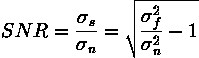
 and
and  are the variances of the true image and the recorded image, respectively.In many cases, additive noise is evenly distributed over the frequency domain (i.e. white noise), whereas an image contains mostly low frequency information. Hence, the noise is dominant for high frequencies and its effects can be reduced using some kind of lowpass filter. This can be done either with a frequency filter or with a spatial filter. (Often a spatial filter is preferable, as it is computationally less expensive than a frequency filter.)In the second case of data-dependent noise (e.g. arising when monochromatic radiation is scattered from a surface whose roughness is of the order of a wavelength, causing wave interference which results in image speckle), it is possible to model noise with a multiplicative, or non-linear, model. These models are mathematically more complicated; hence, if possible, the noise is assumed to be data independent.Detector Noise
One kind of noise which occurs in all recorded images to a certain extent is detector noise. This kind of noise is due to the discrete nature of radiation, i.e. the fact that each imaging system is recording an image by counting photons. Allowing some assumptions (which are valid for many applications) this noise can be modeled with an independent, additive model, where the noise n(i,j) has a zero-mean Gaussian distribution described by its standard deviation (
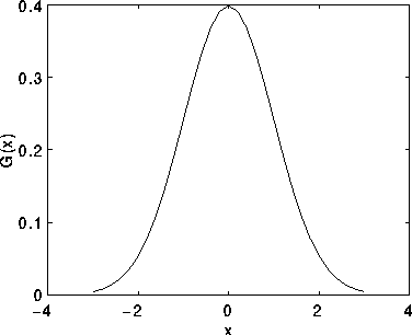
 ), or variance. (The 1-D Gaussian distribution has the form shown in Figure 1.) This means that each pixel in the noisy image is the sum of the true pixel value and a random, Gaussian distributed noise value.
Figure 1 1-D Gaussian distribution with mean 0 and standard deviation 1
Salt and Pepper Noise
Another common form of noise is data drop-out noise (commonly referred to as intensity spikes, speckle or salt and pepper noise). Here, the noise is caused by errors in the data transmission. The corrupted pixels are either set to the maximum value (which looks like snow in the image) or have single bits flipped over. In some cases, single pixels are set alternatively to zero or to the maximum value, giving the image a `salt and pepper' like appearance. Unaffected pixels always remain unchanged. The noise is usually quantified by the percentage of pixels which are corrupted.
Guidelines for Use
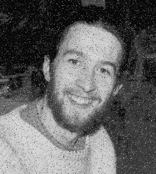
In this section we will show some examples of images corrupted with different kinds of noise and give a short overview of which noise reduction operators are most appropriate. A fuller discussion of the effects of the operators is given in the corresponding worksheets.Gaussian NoiseWe will begin by considering additive noise with a Gaussian distribution. If we add Gaussian noise with
values of 8, we obtain the imageIncreasing
 yields
and

for
 =13 and 20. Compare these images to the original
Gaussian noise can be reduced using a spatial filter. However, it must be kept in mind that when smoothing an image, we reduce not only the noise, but also the fine-scaled image details because they also correspond to blocked high frequencies. The most effective basic spatial filtering techniques for noise removal include: mean filtering, median filtering and Gaussian smoothing. Crimmins Speckle Removal filter can also produce good noise removal. More sophisticated algorithms which utilize statistical properties of the image and/or noise fields exist for noise removal. For example, adaptive smoothing algorithms may be defined which adjust the filter response according to local variations in the statistical properties of the data.
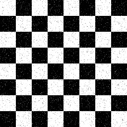
Salt and Pepper NoiseIn the following examples, images have been corrupted with various kinds and amounts of drop-out noise. In
pixels have been set to 0 or 255 with probability p=1%. In

pixel bits were flipped with p=3%, and in
5% of the pixels (whose locations are chosen at random) are set to the maximum value, producing the snowy appearance.

For this kind of noise, conventional lowpass filtering, e.g. mean filtering or Gaussian smoothing is relatively unsuccessful because the corrupted pixel value can vary significantly from the original and therefore the mean can be significantly different from the true value. A median filter removes drop-out noise more efficiently and at the same time preserves the edges and small details in the image better. Conservative smoothing can be used to obtain a result which preserves a great deal of high frequency detail, but is only effective at reducing low levels of noise.
Interactive Experimentation
You can interactively experiment with this operator by clicking here.Exercises
- The image
is a binary chessboard image with 2% of drop-out noise. Which operator yields the best results in removing the noise?
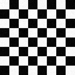
- The image
is the same image corrupted with Gaussian noise with a variance of 180. Is the operator used in Exercise 1 still the most appropriate? Compare the best results obtained from both noisy images.
- Compare the images achieved by median filter and mean filter filtering
with the result that you obtain by applying a frequency lowpass filter to the image. How does the mean filter relate to the frequency filter? Compare the computational costs of mean, median and frequency filtering.
References
R. Gonzales and R. Woods Digital Image Processing, Addison Wesley, 1992, pp 187 - 213.A. Jain Fundamentals of Digital Image Processing, Prentice Hall, 1989, pp 244 - 253, 273 - 275.
E. Davies Machine Vision: Theory, Algorithms and Practicalities, Academic Press, 1990, pp 29 - 30, 40 - 47, 493.
B. Horn Robot Vision, MIT Press, 1986, Chap. 2.
A. Marion An Introduction to Image Processing, Chapman and Hall, 1991, Chap. 5.